
Ever-smaller circuit boards require robust connectors that can stand the test of being installed not only in industrial equipment, but they may also be required for machines that have to work in harsh environments, and connectors for these must comply with MIL-DTL-83515, a US Department of Defense quality and safety standard that governs their design and performance.
They must be robust, durable, have low contact resistance and high current, dielectric strength. They should also withstand at a minimum shock and vibration- as defined by the specifications.
Whether the connectors are part of a circuit board destined for installation in equipment that used on the ground, in air or space, Omnetics have decades of experience in designing these products. They have a standard catalogue of almost off-the-shelf inventory of designs and specifications they can produce to meet a majority of client requirements. A customer just follows a comprehensive process as laid down in the document, decide which of the component and technical parameters meet their needs, order samples to test, and that’s it.
Some of Omnetics’ standard Micro connectors types are:
- Micro strip
- Micro circular
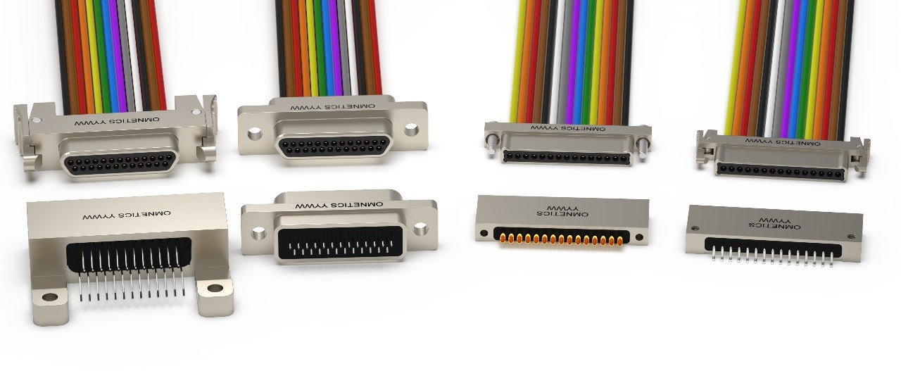
- MIL-DTL-83513 Micro-D
- Micro-D and latching Micro-D
However, if the samples they order need adjustments of any kind, within the capabilities of the unit, Omnetics’ technicians will work with you to ensure that you get exactly what you need. They can provide expert help as they have been doing this for more than 30 years.
In that time, circuit boards and components have dramatically reduced in size, but increased their applicability to a whole host of new uses. Omnetics has kept ahead of this development curve by ensuring their R&D monitored any likely developments in digital technology that might require a change to their range of connectors. Therefore, they reduced sizing to match production materials, designs and other technical considerations such as amperage and signal path routing, as and when the market indicated this was needed.
Higher and higher speed digital signal management relies on properly designed circuit board layouts and signal routing paths to avoid crosstalk, noise and induced electromagnetic interference. Adjacent circuit lines can be adversely affected and develop noise and harmonic disturbance if the high-speed digital signals get too close to each other. Omnetics’ Micro-D connector spacing works for many new digital devices and helps fit more electronics than the previously used larger D-Sub connectors.
At the forefront
Continuously increasing the number of wires capable of being fitted in less space, together with the reducing weight of their connectors (male/female) have kept Omnetics at the forefront of the industry. Micro-D connectors are produced in huge numbers globally due to their standardized materials, shells and inter-locking mechanisms. Another factor in this is that many circuit board design softwares have standardized printed circuit board patterns that match standard Micro-D connector fittings. (MIL-DTL-83513 specification is now the standard for assured reliability and supports multiple suppliers.)
Online modelling work sessions are regularly held by Omnetics to analyze new circuit board layouts to ensure their connectors can fit the new, as well as match standard layouts. Circuit board patterns designed for maximum power and signal performance by the latest chip technology benefit from perfect connectivity using a directly mounted and matching Micro-D connector design.
Standard Micro-D connector types can be selected from online or catalogue listings; some of these are increasingly seen as basic designs that can be modified for any custom fitting a client needs. Shapes, angles, board mounts, cabling and construction material can be altered to suit any system requirements.
Standard Omnetics Micro-D connectors, or customized to fit your needs:
- Check the standard Micro-D types available in the catalog or online.
- Compare them to your own physical and electrical requirements.
- If one fits, request a sample.
- If one is close but needs slight adjustments, contact Omnetics for an online solid modeling session. This should take fewer than two days.
- Work online with the connector designer to match your form, fit and electrical needs. Review and approve the solid models.
- Ask for a 3D model to be made of your new connector, which should take around two days.
- Receive the model and ensure it fits.
- Order the quantity you need.
Further details:
For more information please visit: https://www.omnetics.com/
