
Size, weight, and power (SWaP) is one of the most significant specifications in the definition of a new product, project, or platform for both military and commercial uses. Almost all new advancements must meet the same criteria: they must be smaller, utilise fewer resources, and perform better for system functionality as a whole. In the current social, economic, political, and global situations, a lean system is more desirable.
Engineers in all fields are frequently challenged to accomplish more with less. SWaP connectors, which offer diverse signal and power levels while supporting small, robust, and lightweight circuit designs, are the primary driving factor behind novel interconnects. So, what exactly is SWaP, though, and why is it significant?
NASA and the US military coined the abbreviation SWaP, and manufacturers and designers of connectors have focused on its imperative to create smaller, lighter, more robust connectors with multiple channels. For a variety of reasons, including the necessity to satisfy ever-tighter space limits, electronic engineers in general are pushing for smaller, lighter interconnects. Engineers can reduce the existing footprint without compromising functionality thanks to SWaP connectors.
Faster signals and response times are made possible by these connectors’ ability to maintain shorter, more direct connections. Additionally, vibration is decreased by the smaller cable/connector combinations, which increase stability and performance. The capacity to transport power, data, and signals is crucial, as are size, weight, and power density.
Miniaturisation is accelerating and more needs to be achieved by less
The basic premise for any connectors is its requirement to mate two (or more) devices; is a cable involved — either device-to-connector, board-to-board, board-to-cable, or cable-to-cable? Answering this will define the types of connectors required.
To meet the industry’s ever-stricter requirements and criteria, connector manufacturers are constantly innovating and improving their products. Reducing SWaP, increasing data throughput, and improving ruggedness and reliability are a few of the issues being tackled.
Connectors are the sole practical solution in some applications, such as power transfer. Multiple printed circuit boards (PCBs) are the standard as all devices get smaller and many use a modular approach to design to get goods to market faster. This necessitates the use of an ever-increasing number of connectors. However, as connector makers introduce new items to the market, the selection grows and appears to become more complicated.
Some basic considerations are:
- Is the space for a connector large enough to handle the required current?
- Is there space for the number of contacts or connectors required?
- Has enough space been provided to allow for cooling or additional cooling elements?
Crosstalk
Crosstalk between various signals becomes increasingly problematic as system speeds rise for designers trying to squeeze every last bit of performance from a system. It happens when there is coupling (either inductive or capacitive) between the various signal lines, which affects the integrity of the signal as a whole. Even while this is given a lot of consideration during PCB development, a badly chosen connector might ruin all of that hard work.
Electromagnetic Interference
As connectors are often the entry or exit point for electrical signals from a product or system, they are also potential entry or exit points for unwanted electromagnetic interference (EMI) radiation that can impact the system itself or other systems close by.

Mechanical and environmental issues
During routine operation, connectors are frequently exposed to mechanical strains, particularly if the application in which they are used necessitates frequent plugging and unplugging of cables. The entire assembly, including the connectors, will undoubtedly be susceptible to shock and vibration for many applications, particularly in hostile settings and body-worn devices.
Many connections have features like bosses and threaded inserts that increase mechanical rigidity, enabling them to be fastened securely without requiring the addition of a gluing process in the manufacturing process.
The connector needs to be appropriate for the setting in which it will be used. This will entail checking the operational temperature range supported at the most fundamental level (including any thermal rise due to currents being taken into account).
A particular connector that has been certified for such an environment may be required due to additional considerations like excessive humidity or any aggressive compounds.
Reliability considerations:
- Strain relief using jackscrews, latches, board mount studs, or panel mount studs
- Backshells or hoods for usability, electrical shielding, and mechanical protection
- Retaining walls to enable epoxy resin back potting (the use of a potting compound on the rear of a connector) around the cable connector’s back
- Environmental safeguards, such as dust caps, sealing, or construction to deny entry to materials
Another important factor is how frequently the connector will be mated and unmated. User-accessible connectors may undergo thousands of mating cycles, particularly in applications like charging portable equipment and body-worn devices.
As a result, the plating material used on the contacts, including the actual substance and plating thickness, must be appropriate for the application.
Other subtle but crucial factors must be considered in extremely demanding applications, such as space or medical technology. For instance, when a connector is used in a vacuum, outgassing from the insulator material or epoxy can have long-term effects for the nearby equipment, making lower outgassing properties more desirable.
Well-defined procedures
For more than 30 years, Omnetics has produced Mil-Spec connectors. The procedure of injecting insulated polyurethane cables over moulds makes its connectors even more robust and impermeable.
These circular connectors, which have been used in numerous military applications, have a flat black overmould that enables a seamless IP68 seal with signal integrity to match.

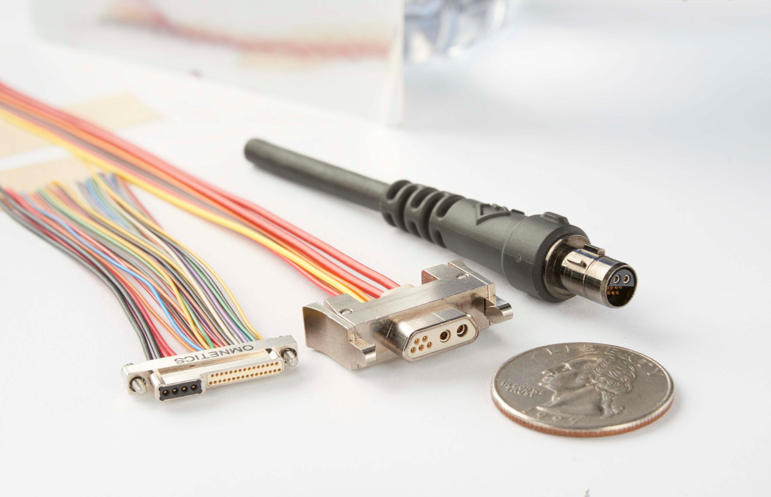
Some of its SWaP connector types are:
- Hybrid Nano-Ds – for software-defined radio (military & satellite)
- Hybrid Micro-Ds – used for a variety of applications such as avionics, body-worn military devices, space vehicles
- Hybrid Circular – body-worn networking hubs for communication and soldier-worn computers
Each high-speed design also makes use of the proprietary Omnetics flex-pin contacts with gold plating, which are polarised and covered by a special insulator made of liquid crystal polymer. The overmoulded shells are keyed to provide one-handed field mateability (gloved or bare). Omnetics’ ruggedized shells use polarised triple-key combinations to make even the challenging connection seem easy, thus blind-mate-ability is no longer a problem.
A 360° shielded solution is concealed completely inside the polyurethane mould and terminated to a banding platform built into the shell to guarantee the maximum level of signal integrity.
Omnetics’ designers produce a wide selection of mixed-signal hybrid connections in addition to altering pre-existing designs. By using just one cable and connector to carry both power and signal in the same system, size and weight are drastically reduced. Additionally, these innovative hybrid connectors are modified to fit the required application.
